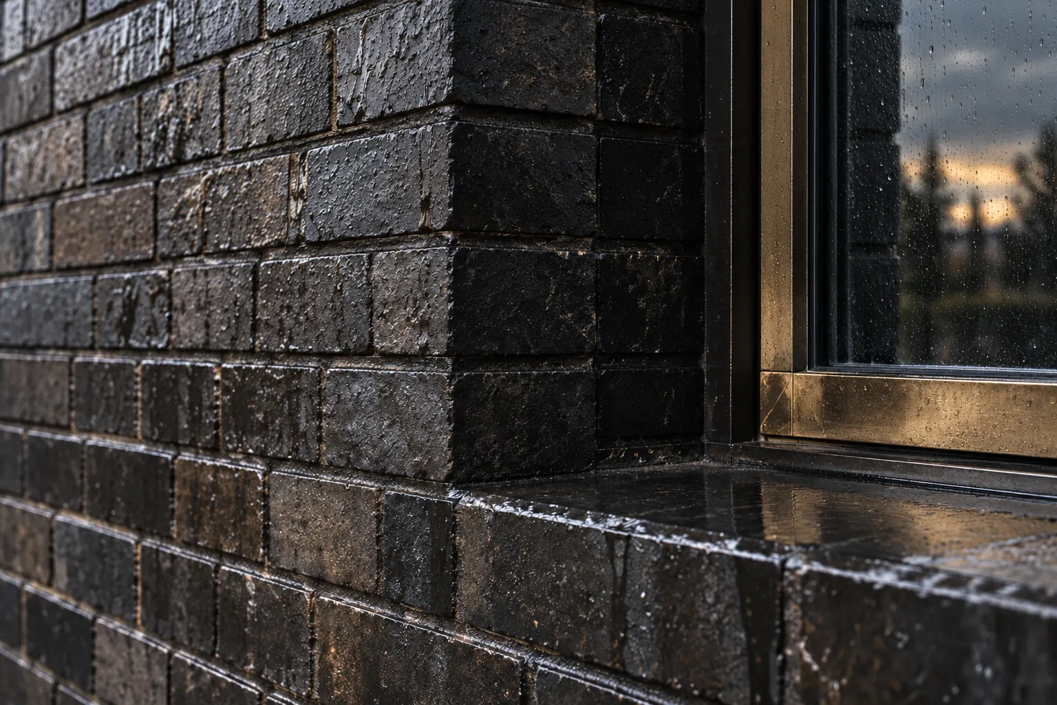
In brief
A three-layer clinker wall – the Polish name for a cavity wall: a loadbearing leaf, mineral wool, an air cavity and a facing leaf of brick carried on brackets – is an external wall where most of the outcome is decided in the structural design, long before the first pallet of brick arrives on site. Fired brick grows while reinforced concrete shrinks, so the facing leaf gets its own support every storey or two, an empty joint is left under every bracket, and the movement-joint drawing is made before the brick is ordered. The brackets are anchored into reinforced concrete, so the design has to settle one thing: that wherever a support is to go, that concrete actually exists and a bracket can be anchored into it securely. The cavity behind the brick is drawn at 40–50 mm so that, after tolerances and the mortar squeezed out of the joints, at least 20 mm is left in it for water to drain, and over every window and every bracket lies a cavity tray with turned-up ends. Most of these things you will not see again once the wall is closed, which is why we inspect them in stages, and every layer that will disappear within a week is photographed.
Where the brackets under the brick come from
A clinker facade comes up very early in the conversation about a residence, usually as one of the first aesthetic decisions, long before the structural drawings. On site that facade is built almost last, more than a year later. Whether it will stand straight and dry for the next several decades, though, depends on drawings made at the very beginning. That is why I describe here the things that have to be drawn before the first floor slab is cast, and a few decisions that are yours.
Not every residence has a brick facade. When one does, I sometimes build it in this arrangement: from the inside, a loadbearing leaf of masonry or reinforced concrete, mineral wool on it, then an air cavity, and on the outside a leaf of solid clinker brick – clinker being the name used in Poland for a dense, hard-fired facing brick that takes up very little water. That brick does not stand on the foundation for the full height of the house. The bottom section stands; the higher parts hang on stainless steel brackets anchored into the edges of the floor slabs, and each level of support carries its own section of wall. The whole leaf is tied back to the loadbearing wall with wall ties that pass through the wool. From the road it looks like an ordinary brick house, and under the brick there is a structure with its own calculations and its own drawing.
I will add straight away that at 2–3 storeys nobody requires brackets. Brick manufacturers in markets where this technology is everyday practice allow a facing leaf to run without intermediate support up to 4 storeys or 12 m in height, with conditions on the thickness of the leaf, the ties and the exposure, and a residence usually fits within that. Brackets are therefore a design decision, and you need to know what they are for. I have three reasons.
The first is the physics of two materials. Fired brick comes out of the kiln completely dry, and from that day it takes up moisture from the air and swells. That movement cannot be reversed and is fastest in the first years; on top of it comes the ordinary movement with temperature. Brick manufacturers tell you to allow about 1 mm per metre of wall in total over the life of the building. Over the same time the reinforced concrete frame does the opposite: it dries out, shrinks and creeps – that is, it slowly deforms under a constant load. One material grows, the other shrinks, and the difference adds up with every metre of the height of the house. Over three storeys that is already several millimetres, and in a joint mortared up solid, several millimetres means a crack. Support every storey or two cuts the facing leaf into sections, each of which moves on its own and has somewhere to take up its movement.
The second reason is the architecture people build residences for. A ground floor glazed across its full width, an upper floor that overhangs, a terrace cut into the body of the house – in places like these the brick has nothing to stand on. A widened footing under the facing leaf is enough for a single-storey house with four windows. Where several metres of brick are to hang over a window 6 m wide, it is not. The third reason only shows in the thermal calculations: a widened footing is solid concrete linking the structure of the house with the zone at ground level, which makes it a thermal bridge that cannot be broken. A bracket with a thermal break pad can be calculated and entered in the heat balance.
All of this leads to one practical conclusion: a brick facade on brackets is part of the structural design. We do not cast anchor channels into the slab edge; we anchor the brackets into the reinforced concrete. What we do make sure of is that wherever there is to be a support, or a rail, the reinforced concrete is actually there – so that there is something solid to anchor into. This is exactly the decision that cannot be put off: if masonry turns up at a support point instead of reinforced concrete, or a ring beam of a different section (the ring beam being the concrete band cast around the walls at each floor), there is nothing to bolt the bracket to, and putting that right is already a change after the concrete has been poured. So before the structural engineer calculates the floor slabs, I sit down with him and the architect over four drawings: the layout of the brackets and support points, the layout of the ties on the elevations, the movement-joint drawing and the detail over every large opening. The design submitted for the building permit usually does not contain them, because it does not have to – this is the construction-detail level I wrote about in the text on coming with a finished design and an architect.
Sometimes we do build it this way, and then we look after every technical aspect of it: the proper fixing of the resin anchors into the concrete, the brackets themselves and the right ventilated cavity behind the brick. I describe these three things below, one by one, because each of them can ruin the wall on its own.
How much cavity is really left behind the brick
Polish building guides give the air cavity as 2–4 cm and usually stop there. What they lack is a distinction that changes how you read the drawing: the designed cavity and the effective cavity are two different things.
You can see the mechanism on any site. The bricklayer presses the brick down, mortar squeezes out of the joint at the back and sets in the cavity as hard ridges – on site they are called snots. Add cut bricks that stick out a few millimetres at the back, and wool that is not perfectly flat either. That is why the Dutch brick industry, with a hundred years of facing brickwork behind it, tells you to draw at least 40 mm, so that 20 mm of clear space is left in the finished wall. And it adds a sentence you rarely hear in Poland: the wool must not touch the brick anywhere. Wherever it does, water running down the inside face of the facing leaf has a bridge into the wall.
I insist on a cavity of 40–50 mm: 40 is the bottom of the range, 50 is the safe standard, and on a tall, dark elevation facing the weather more does no harm. In countries where brick facades are the norm, the range runs from 40 to 75 mm depending on exposure: the less sheltered the wall, the more air behind the brick.
The second decision about the cavity is this: what is it actually for? One school treats it purely as drainage – openings at the bottom and above the trays so that water has a way out, with air movement as a side effect. The other treats it as a ventilated space: open joints at the bottom and at the top, the sun-warmed brick turns the cavity into a chimney, and the chimney draws the moisture out. Both work, but they are looked after differently: with drainage, the cavity has to be wider and absolutely clean; with ventilation, every horizontal interruption needs an inlet and an outlet, because a lintel, a bracket or a tray breaks the draught. In a residence, where the facing leaf is cut by brackets every storey, that means each section of wall breathes separately and each has to have this drawn.
While we are at it, a question almost every architect asks about this wall: does the facing leaf insulate? With a well-ventilated cavity it does not, and that is fine, because the wool does all the thermal work and the brick shields it from the weather. For the same reason I do not let anyone talk me into filling the cavity with wool for a few extra centimetres of insulation. It would indeed be warmer, so the person suggesting it is partly right; but the wall would lose the space in which it dries after rain. In a sheltered exposure that can be defended. On open ground, where rain can come in sideways, I treat a clear cavity as non-negotiable.
Open joints – the vertical joints deliberately left without mortar so that the cavity is connected to the outside – are needed in greater numbers than intuition suggests. At the bottom of the wall you leave roughly one for every two or three bricks, plus a row above every tray and at the top of the wall. On an elevation 24 m long that comes to about 50 open joints along the bottom. A few little holes over a whole wall give you neither drainage nor draught.
Water has to get through the brick and out again
The hardest thing to accept about this technology is this: a facing brick leaf is not a barrier to water, and nobody designs it as one. Driving rain gets through the joints, and where the joints are not properly filled it can reach the other side within minutes. The wall works because the water that has got through the brick has somewhere to go: it runs down the inner face, lands on a tray and leaves through the open joints. Everything else in this section is about things you cannot see on the finished facade, which is why they have to be looked at before they are covered up.
A tray lies over every interruption of the cavity: over a lintel, over a bracket, under a sill, at a flat roof. It has to be in one piece over an opening, joined with sealed laps on long runs, taken a dozen centimetres or more up the loadbearing wall, laid to fall towards the outside, and finished with ends turned up to close it at the sides – stop ends. A tray without stop ends works like a gutter without sides. The water runs to the end, spills into the cavity beside the window, and a year after moving in someone wonders where the stain on the reveal came from. In proprietary support systems this detail is sometimes part of the manufacturer’s solution, and then I inspect it with the system documentation in hand.
At the bottom of the wall the facing leaf has a damp-proof course at least 15 cm above the ground and a base tray, above which the first row of open joints begins. The cavity itself runs down below that tray, so that whatever falls to the bottom over the years does not block the water’s way out. And here is the first of the moments when I stand next to the bricklayers: the bottom of the cavity can be cleaned only if a few bricks are left out of the first course while the wall goes up. They are put in at the very end. Without that, a little heap of mortar stays at the bottom and sits there for the next 50 years.
Mortar that falls into the cavity does damage in several places at once. It settles on the ties and clogs the drip, and then water travels along the wire to the loadbearing wall. It can build up on a tray into a hard dam behind which water stands instead of leaving. And if it lands on the top edge of the wool, the wool gets wet and stops insulating. Once the wall is closed, you cannot check any of this except with a borescope through a drilled hole. That is why I require what in countries with a long brick tradition is simply standard workmanship: a board hangs in the cavity on the ties, lifted course by course and cleaned, and mortar is cleaned off the wall as the work goes, while it is still soft. Devices that catch mortar above the trays help, but they do not replace clean work.
The movement-joint drawing comes before the brick is ordered
How do you know how much a wall of a particular brick will grow? Its manufacturer knows, and that is what I ask about when the product is chosen. There is one surprising thing here: water absorption tells you nothing about it. A clinker brick that takes up almost no water can grow as much as an ordinary soft brick, because the movement is decided by the clay it was fired from. That is why in the specification I ask the manufacturer for the moisture movement value of the actual brick, rather than guessing it from an absorption table.
To show the scale: an elevation 24 m long, at about 1 mm per metre, will grow by about 2.5 cm over the life of the building – as much as two mortar joints together. That movement will go somewhere. With movement joints every 8 m, each one takes a few millimetres and nothing happens; without them the wall finds a place for itself: in a corner that opens up, in a stepped crack from the corner of a window, in a bulging band of brick over the windows.
Now the numbers, because a good deal of confusion has grown up around them. Someone may tell you that movement joints in the facing leaf have to be every 8 m, because that is what the standard says. And he will be partly right, because that figure really is in the standard. Except that it sits in the row for calcium silicate masonry. Clay brick has 12 m in the same table, the first joint goes no further than half that distance from a restrained corner, and the last word belongs to the designer anyway. On top of that, some Polish websites quote an old masonry standard withdrawn many years ago, and that is where all the confusion comes from. Practice in the countries with the most brick facades stays close to these values: 10–12 m as the standard, in no case more than 15 m, and more caution where there are many openings, with spacing down to 6–8 m. Interestingly, those countries do not agree on whether the colour of the brick matters here. Some tell you to put the joints closer together on south-facing walls of dark brick; others say colour plays no part. I do not take it upon myself to settle that. With black clinker facing south I simply require closer movement joints, because a black wall heats up in July like the bonnet of a car, stands in the frost in winter, and the masonry has to take up the movement from that whole swing in temperature somewhere.
The width goes hand in hand with the spacing. Practitioners in countries with a long brick tradition work it out simply: the width in millimetres is roughly the spacing in metres plus 30%. A joint every 12 m therefore comes out at about 16 mm, clearly wider than a mortar joint. If it is to be 10 mm and disappear into the rhythm of the joints, the spacing comes down to 7–8 m.
The movement-joint drawing itself is more than a line every 12 m. The first joint from a corner has to be closer than half the spacing, because two walls expand towards each other and a few millimetres of combined expansion are enough to crack the corner. Short returns of wall, narrower than about 70 cm, get a joint or a slip detail. Narrow bands of brick above and below ribbon windows move the most in relation to their height, so the spacing there is halved. Parapets and walls with nothing on top of them likewise, every 5–6 m. Then there are changes in the height of the elevation, changes of support and changes of material. The drawing is made by three people: the structural engineer calculates, the architect decides where the lines may show, and I make sure it can be built and then looked after.
There is one more movement joint that Polish texts say nothing about, and with brackets it is the most important one: the horizontal joint under every bracket. The brick below a bracket grows upwards; the structure above it settles downwards. If the joint between the top of the wall and the underside of the steel angle is mortared up for the sake of an even joint pattern, the brick has nowhere to grow and starts lifting the steel. First the edges of the bricks under the toe of the angle crumble, then the panel bulges, and in extreme cases the bracket goes up together with its bolts. At least 10 mm of empty joint is left under the bracket, and the rule of thumb says 1 mm for every metre of wall below. It is filled with a compressible material and sealed only after it has been inspected. Sealed too early, it looks from the scaffold exactly like a joint that has been mortared up, and the difference shows only years later – in cracks, unfortunately.
A vertical movement joint is filled with a compressible material to roughly half its depth and closed with an elastic sealant, because mortar in a movement joint cancels it out entirely. And if you are worried about how these lines will look – almost every architect asks about that too – then a sealant matching the colour of the mortar, with sand scattered on it while it is fresh, at a spacing of 7–8 m, simply disappears into the rhythm of the joints. A joint can also be hidden in an internal corner or at a change of height. Hiding one behind a downpipe is less straightforward, because the pipe’s fixings have to let the wall move, and one day someone has to get back to the joint itself for maintenance. One thing I do not allow: a movement joint stepped along the bond of the bricks. Debris stays in a broken joint like that, and the sealant works in shear and tears, so a movement joint has to be a straight vertical line. Bed joint reinforcement helps around openings and lets the joints be spaced further apart, but it does not replace them.
This drawing has to be ready before the brick is ordered, and that is not a formality. What will be built and how, we discuss well in advance, because the drawing decides how much brick we order from a single batch and where a line may go at all. Once the order is placed, it is too late to change any of that without losses.
Brackets and ties are calculated by the structural engineer
A residence with about 600 m² of facing brick carries more than 100 tonnes of brick, counting a typical weight per square metre for a solid facing leaf, and has 3,000–4,000 ties in its walls. I give these figures so that you can see what class of structure we are talking about, because from the road it looks like the most ordinary wall.
A bracket carries the brick on the toe of an angle, and it has its rules. The brick has to bear on the toe over at least 2/3 of its width, and the overhang of the first course past the edge of the support is limited to 15 mm or so – that is the figure the masonry standard gives. A bracket can be adjusted in three axes, and that is its strength; the adjustment has limits, though, because shims cannot be stacked up endlessly, and the thermal break pad eats into that allowance. The fixing is tightened with a torque wrench, the torque goes into a written record, and resin anchors get pull-out tests. Suppliers of support systems all say that the most common mistake on site is brackets fitted by bricklayers in passing – no torque, the wrong bolt, by eye – and a panel that drops within a year. That is why I require that record when the brackets are inspected.
The material is one of the points I do not give way on: the brackets and ties are stainless steel. Galvanised ties are no longer accepted in new cavity walls in countries where brick facades are the norm, because in a cavity the zinc coating wears away within one to several decades, and rust takes up several times more space than steel and bursts the joints from the inside. In an aggressive environment, near the coast or near industry, the steel grade goes up a class. In the Polish climate, apart from those two situations, standard stainless steel is usually enough, but that decision has to go into the specification.
The tie itself has its geometry too. The strictest school calls for wire no thinner than 4 mm, embedded at least 5 cm in the joint, and the type and length of the tie follow in any case from the approval of the particular system. In the middle of the cavity sits the drip – a disc or a kink from which a drop is meant to fall into the air instead of running along the wire to the wool. The tie lies level or with a slight fall to the outside; tilted inwards, it leads water over the drip straight into the wall. Ties are not bent on site when they turn out too short, because a bent tie loses its capacity and its approval. And one thing that becomes a separate item in the design of a residence: with 20–25 cm of wool plus a 5 cm cavity, ordinary one-piece ties are no longer enough in compression, and two-part or special ties come in, approved for that distance between the leaves.
How many ties go into a square metre? This is where the tables differ most: from 2.5, through the Polish minimum of 4–5, to 7 in the most cautious, with an extra 3 per metre along every free edge – at a reveal, a corner, a movement joint and the top of the wall. The difference comes from the wind zone and the stiffness of the facing leaf, which is why for a residence on open ground the number of ties is set by the structural engineer for the particular zone and height. The table is the minimum you start from. At movement joints only slip ties go in, which let the wall move lengthways, and in the band above and below a bracket the ties are placed closer together.
That leaves the question of heat. Steel crossing the wool conducts it incomparably better than the wool does, and that cannot be avoided; only the scale can be limited. A continuous steel angle without a thermal break can, according to North American research, eat up about half of the insulation’s effectiveness along its line. Individual brackets, with the wool running on behind them, leave losses of between 10 and 20%. The order of priorities I hold to in the design is simple: stainless steel instead of carbon steel, because it conducts several times less, as few fixings as possible, thermal pads of a material that does not creep under constant load, and individual brackets instead of a continuous angle wherever the structural engineer agrees. With two levels of brackets and a 100 m perimeter, we are talking about 200 m of linear thermal bridge. That is why a bracket is not chosen from a catalogue by price. And this is one thing you can ask the designer about, even if you know nothing else about facades.
A large window in the facing brick
Windows in residences are 4, 5 or 6 m wide, and above them there is to be brick, with no visible concrete and no visible steel. It can be done well, provided it is known from the start what carries that brick.
Up to about 3.5 m the matter is usually settled by system lintels: a stainless steel element with slips of the same brick bonded to it in the factory, which from outside cannot be told apart from the wall; the permitted spans and conditions of use for each such unit come from its manufacturer’s documentation. Beyond that width, the brick over the opening hangs on a bracket fixed to whatever is above the window – a beam, the slab, the concrete – and the brick soffit is a lining of that support: a panel of brick slips on a frame, a precast unit faced with brick from the same batch, or masonry reinforced in its bed joints. The sources give no ready figure for how much brick can hang, and on what, because the structural engineer calculates that from the tables of the particular system. The limit to remember is a different one: an opening wider than about 3.5 m is a structural decision in the design. Nobody will make it well once the bricklaying has started.
Why not an ordinary steel beam, since steel will carry anything? Because masonry above steel does not forgive deflection. A beam under a floor may deflect by 1/360 of its span and be within the standard. The deflection of a support under brick is limited to 1/500–1/600 of the span, with the rotation of the toe checked separately. Over a 6 m window that is the difference between about 17 mm and 10 mm, and in the stricter version a hard 5 mm applies, whatever the span. A beam that is within the standard for the structure will crack the masonry above it long before it comes anywhere near its own limit. On top of that, the bearing on each side of the opening is longer than with an ordinary lintel – 10–15 cm, and more at wide openings – with a gap at the ends, because steel moves with temperature more than brick does. Over the whole thing lies a tray: one piece, a fall, stop ends, at least two open joints. This detail is photographed before it is bricked in, because after a leak over a window there is no way left to establish whether the tray was there at all.
The window itself stands in the plane of the wool. The frame overlaps the insulation by at least 3 cm, in practice more if the reveal detail allows it, sits back from the face of the brick and is fixed to the loadbearing wall through a sub-frame, because large-format aluminium glazing weighs too much for ordinary frame anchors. It is not fixed to the facing leaf, because the leaf moves and the window should not move with it. The cavity at the reveal is closed with an insulated closer so that rain does not get in from the side. A window pushed too far out has its junction with the brick standing in the rain; set too deep, it leaves a bare brick reveal – and wet brick insulates noticeably worse than dry – and a cold frame on which vapour condenses. The sill projects beyond the face and has a continuous drip. Without a drip, water runs back along its underside and draws a dark moustache under the window, which you will see from the drive every day. The junction of the sill with the reveals is a detail where the sealant will age one day, so it has to be drawn in such a way that its ageing does not mean water in the wall.
Brick and mortar are chosen as a pair
We talk about the brick itself before it is ordered, because a few of its properties change the details of the whole wall. Frost resistance in the highest declared category and a low salt content are the starting point for a facade that stands wet and freezing for half the year. Water absorption is more interesting: clinker usually takes up just a few per cent of water, which is good for durability and a nuisance for the bricklayer, because such a brick does not draw water out of the mortar and slides about on it. So the mortar is matched to the particular brick, following its manufacturer’s recommendations. There is one rule common to every school: mortar stronger than the brick will crack the brick instead of itself. Low absorption also changes the path of the water. Since the brick takes up little, more rain runs down the face and through the joints, so with clinker the trays and the open joints matter even more than with an absorbent brick.
The joints can be finished as the wall goes up, filled full and compacted with a jointing tool, or raked out to about 15 mm and pointed later, which gives better control of the colour. There is one condition: the pointing has to bond with the mortar behind it, because a void behind the pointing is a ready-made path for water. Countries that have been laying brick for a hundred years still argue over the shape of the joint, concave or weathered, and I will not settle that argument. I watch for one thing: the joint has to shed water, not form a ledge where rain stands. That leaves the colour. Brick is blended from at least 3 pallets at a time, because batches differ in shade, and a wall laid pallet by pallet comes out striped. You see the stripes only from a distance and in full sun – that is, when nothing can be done about it any more. The width and colour of the joint, and how the brick will work with the whole building, we choose on photorealistic visualisations rather than on a trial piece of wall, because even a 2 × 2 m panel will not show the house with its shape and its windows.
I check the material when it is unloaded, not when it is already in the wall. With brick I look at whether the batch we ordered is the one that arrived, whether the pallets carry their labels and whether they have been standing uncovered in the rain for a week. Wet brick can be laid and nobody will see it until the facade starts to dry out in stripes.
What I watch on site before the layers disappear
Ties, trays and brackets are work that gets covered up soon after it is done – the Polish term translates as disappearing work. You have to agree with the site manager on inspecting it in several stages, because if it is done wrong it will be very hard to put right. On an ordinary house that rule applies to a few things. On a residence with a brick facade it applies on a scale you do not see from outside: there are several thousand ties, each meant to hang with its drip in the air, plus hundreds of metres of trays and dozens of brackets with their tightening torque on record. All of it disappears under the next layers within a few weeks of being done. That is why a brick facade is inspected while it is being built, at seven points:
- Damp-proof course and base tray. Height above the ground, laps, stop ends, the first row of open joints, the cavity running down below the tray. A photograph before it disappears.
- Ties before the wool. Number per square metre, extra ties at the edges, depth of embedment, the drip in the middle of the cavity, level or with a slight fall outwards. This is the only moment when the ties can be seen whole.
- The wool. Boards made for cavity walls, water-repellent and non-combustible – in a cavity that draws like a chimney, non-combustibility is not a detail. Butted tight, with staggered joints, pressed to the wall with clips on the ties, because air circulating in a gap between the wool and the wall is a loop that carries heat away. It is the same physics that rules out sticking insulation boards to a wall with a few dabs of adhesive. A wind barrier over the wool is usually not needed, because air movement behind a well-ventilated facing leaf is slow enough to make no difference with boards of decent density. If the wool manufacturer requires a facing fleece, its data sheet overrides this paragraph. The top edge of the boards clean, the cavity clear.
- Brackets. Position and level, reinforced concrete at every support point, the fixing of the resin anchors, the tightening torque on record, shims within the allowance, thermal break pads, pull-out tests. Signed off by the structural engineer.
- Trays over every opening and every bracket. One piece, a fall, stop ends, at least two open joints above each. A photograph.
- Movement joints. Vertical ones empty before filling, with slip ties. The horizontal one under each bracket empty before sealing, checked by hand. Sealant at the very end.
- Protection. Fresh masonry covered for at least two days, with the sheet kept off the face, because under sheeting that touches it the wall sweats and stains are left; bricks on pallets above the mud; sills and temporary downpipes on as soon as the bricklaying is finished; cleaning only by the method the brick manufacturer gives.
To that I add two things I have done for years with ordinary walls, which count double with a facing leaf. The first is an inspection after just a few courses, before the crew goes any higher, because a mistake caught at the start takes the least work – and the least stress – to put right.
The second is the yardstick a facing leaf is measured by in the first place. The structural tolerance – 20 mm out of plumb per storey – is far too loose for a facing leaf. Workmanship guides measure it separately: 8 mm over a 5 m straightedge, bed joints within 1.5 mm of the average, judged from 10 m away. With brick, no render will cover the unevenness afterwards.
Weather has its thresholds with a facing leaf. Polish crews stop wet work at around +5°C, and I respect that limit in the schedule. Countries with a longer tradition draw the line more precisely – down to about 3°C on a falling thermometer and from 1°C on a rising one – but none of them accepts antifreeze admixtures in the mortar. So the facing leaf of a residence is not built in winter, and there is room for that in the plan from the start – I wrote about it in the text on the two years a residence takes. Heat has a threshold on the other side: above 30°C the bricklaying is done in the shade, mortar in the sun is finished within two hours, and bricks are not wetted by guesswork. An absorbent brick is dampened; low-suction clinker is not dampened by default, because the manufacturer’s data sheet decides.
And the rule that ties these seven points together: each of these layers is photographed before it disappears, and how those photographs reach you I described in the text on living alongside the build. Once the wall is closed, the only way to look inside is with a borescope through a drilled hole, so the photographs are the only complete record of what is really in it.
How to tell that someone skipped this
Brick facades fail in repeatable ways, and after a few years they show by themselves what they were missing. This list is useful when you choose a contractor, because it lets you check whether a crew really knows these mechanisms before it lays a single brick for you. The point is not to diagnose other people’s houses from the pavement.
Horizontal cracks in the joints, repeating every few courses, with rusty streaks – the ties: galvanised, or caked in mortar that held water against them. Vertical cracks at the corners and at even intervals along long walls, stepped cracks from the corners of windows, a corner pushed out of line – movement joints that were missing or too far apart. A horizontal crack at floor level with spalled bricks under the angle – the joint under a bracket mortared up. Wet patches over the windows after rain and plaster coming away from the reveal inside – a tray without stop ends, or blocked open joints. Damp in the wall for no obvious reason and wet wool – a cavity full of debris, or ties sloping inwards. Efflorescence that comes back every year – a constant supply of water, meaning drainage that does not work. Stripes of colour – bricks laid pallet by pallet. Cold reveals and condensation around the windows – the window outside the plane of the insulation. A face that flakes off – brick with too low a frost resistance where the wall stands saturated: a sill, a parapet, a plinth.
A contractor who answers a question about a crack with “that is settlement, every house settles” simply cannot tell these things apart. One who says “horizontal and regular is the ties, vertical at the corners is movement joints, diagonal from an opening is the lintel or the ground” has seen them on so many walls that he will recognise them on yours too – ideally before they appear.
The inspection points in the list above exist so that the crew’s work is checked at set moments and against set criteria, instead of by looking over their shoulders.
When clinker on brackets is not worth it
Not every building needs this arrangement, and I would rather say so before the design exists. I see three such situations.
The first: a low building, single-storey or with one floor above the ground floor, with short elevations, ordinary windows and no overhangs. A facing leaf like that can stand on a widened foundation for its full height, and brackets add nothing to it. What remains is the cavity, the ties, the trays and the movement joints – most of this text – but without the elements in the slabs. The arrangement is simpler and the effect the same; there are fewer things to get wrong. Only the thermal bridge at the footing then has to be calculated separately.
The second: a sheltered elevation – between buildings, on a side with no wind and no driving rain – forgives more than a wall standing in open country. The cavity can sit at the lower end of the range and the rules for openings can be gentler. The residences I talk about usually stand on the harsher side of that map, so that is the one I take as my starting point. But if your plot is sheltered, there is no reason to pay for the full regime against conditions you do not have.
The third situation is a different class of solution: brick slips bonded onto external insulation, with no cavity and no brackets. From a distance it looks similar, but it is not masonry. It is a cladding that hands its weight to the adhesive and the fixings and carries water on its face. If your facade is to have decorative elements – composite or natural timber boards, clinker slips or imitations of them, decorative stone, architectural concrete or metal sheet – then it pays to settle right at the start, before the polystyrene is ordered for the site, exactly what is to be done and how. Slips are extra weight, so the insulation under them has to be mechanically fixed, and fixings cannot be added after the fact. On a standard house this can be a sensible choice. On the main elevations of a residence I advise against it, because it does not give you what you choose brick for: the durability of a solid wall and an ordinary mortar joint rather than grouted joints between slips stuck on with adhesive. But on an outbuilding or a low garden wall there is no point building a cavity wall just for the sake of consistency.
I will also say what I do not promise. A facade without a single white patch in its first season – the salts from the mortar come out with the rain and go with the rain, and only efflorescence that returns every year is a defect. A facade without movement joints – they can be hidden in the rhythm of the joints and in corners, but whoever promises a brick wall without movement joints is promising cracks in places chosen by chance. Laying the facing leaf in winter to meet a deadline. And I do not promise that this text will do instead of a design: I am not a structural engineer, and I do not calculate brackets or lintels. I make sure they are calculated by someone who does it professionally, and that exactly what he calculated ends up in the wall.
What I ask before I say yes
I ask these questions about every residence with a brick facade – of the architect, of the structural engineer and of myself. If any of them has no answer, the facade design is not finished, however it looks in the visualisation.
- Does the facing leaf have intermediate support, and where – and at every support point, is there reinforced concrete into which a bracket can be securely anchored, before the slab formwork goes up?
- How much cavity is on the drawing, and how much of it will be left after mortar snots and tolerances – was the effective cavity worked out, or only the designed one?
- Is there a movement-joint drawing – spacing, width, the corner rule, the horizontal joint under every bracket – signed by the structural engineer and accepted by the architect?
- Is there a tie drawing: how many per square metre for this wind zone, where they are closer together, which type for this cavity width, where the slip ties go?
- What carries the brick over every opening wider than 3.5 m, and for what deflection was it calculated?
- Where are the trays and the open joints – over every opening, over every bracket, at the base – and who will photograph them before they are bricked in?
- Does the brick have a declared frost resistance in the highest category, a low salt content and a moisture movement value given by the manufacturer – and is the mortar matched to that brick?
- Has the crew built on brackets before, and can it say which cracks come from ties, which from movement joints and which from a lintel?
Questions about working together – from the budget to how payment works – I answer in the Questions section.
Frequently asked questions
Does a clinker cavity wall still need an air gap when it already has wool in it?
Yes, because these are two different functions: the wool holds the heat, the cavity drains away the water that has got through the brick, and neither can replace the other. Filling the whole cavity with wool is sometimes accepted in places sheltered from driving rain. On open ground I require a 40–50 mm cavity and make sure that clear space remains in it once the wall is built, because otherwise the wall has no way to dry out after rain.
Is white efflorescence on a new clinker facade a defect?
In the first season, usually not – the white deposits are salts, mostly from the mortar, which come to the surface with water and wash off with the following rains. They are brushed off dry; pressure washing drives them back in. Efflorescence that comes back year after year is a defect, because it means a constant supply of water into the wall. Chemical cleaning is done only by the method the brick manufacturer specifies, because acid on a light-coloured brick can leave permanent discolouration.
Why is an ordinary steel lintel not enough over a large window?
Because the masonry above the steel cracks before the steel deflects as far as its standard allows. A support under brick is designed for a noticeably stricter deflection than a beam under a floor: over a 6 m window that is a difference of about 17 mm against 10 mm, and in the stricter practice a hard 5 mm applies, whatever the span. Up to about 3.5 m, system lintels with brick slips are usually enough; beyond that, the brick hangs on a bracket fixed to the structure above the opening, and how far it can reach is calculated by the structural engineer.
If the residence you are thinking of is to have a brick facade, come to me with it before the structural engineer draws the floor slabs – at that stage the brackets, the supports and the movement joints are still only a drawing. Let’s talk about your project.